

Three types of coax cable (RG-6, RG-11, RG-59) are used for connecting an antenna to televisions. These cables have a 75 ohm (Ω) impedance, use F-type male connectors, and have 1 to 4 layers of shielding. More shielding has better immunity from interference and is a little more durable, but is a little more expensive. The more shields the better, especially for outside cables.
RG-6
coax cable
This cable is the industry standard for home reception. and is available with 2, 3, or 4 layers of shielding. Four layer shielding should be used for outside cables.
RG-11
coax cable
This cable can be used if signal loss is a problem, typically a long cable run. The advantages are it has the least loss, and can also carry high power signals. The disadvantages are it's more expensive, less flexible, bigger and heavier. This cable is primarily designed for high power transmissions and long cable runs.
RG-59
coax cable
This cable can be used, but is a little more lossy and has only a single layer of shielding. It's usually used indoors for raw video signals (recorders, games, etc.). RG-59 was used for over-the-air, cable, and satellite TV before RG-6 became common.
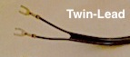
Twin-lead
cable
This cable is sometimes called flat or ribbon cable, and should be replaced with coax. Twin-lead works well for VHF frequencies (RF 2-13) and is especially good at the VHF-Lo channels (RF 2-6), but is not suitable for UHF channels (RF 14 and higher). Additionally it does not have any shielding.
All cables have some signal loss that depends on cable type, length, and frequency (RF Channel). The longer the cable and the higher the frequency, the greater the loss. Radio frequency channels in the VHF band (RF 2-13) have noticeably less loss than RF channels in the UHF Band (RF 14 and above). Loss is measured in decibels (dB's).
|
Cable Type Cable Length Radio Frequency Band |
| TV Coax Cables | |||
|---|---|---|---|
|
VHF / UHF (RF 2 - 36) 75 ohms (Ω) Impedance F-type male connectors |
|||
| Coax Type |
Loss
dB / 100 ft |
Shield Layers |
Primary Use |
| RG-6 | -5 dB | 2, 3, or 4 |
TV Reception Industry Standard |
| RG-11 | -3 dB | 2, 3, or 4 | High power signals or long cable runs |
| RG-59 | ≈ -6 dB | 1 | Raw Video or TV Reception |
| Twin-lead Cables | |
|
VHF (RF 2 - 13) 300 Ω Impedance Blade connectors |
|
| Loss dB / 100 ft |
Primary Use |
|---|---|
|
-1 dB ( VHF-Lo ) -4 dB ( VHF-Hi ) |
VHF Signals |

|
Coax Cable Loss Calculator |
|
|---|---|
| Frequency Band: | |
| Cable Type: | |
| Cable Length: | |
|
Frequency Band | |
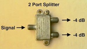
A coax cable Signal Splitter is used to connect to multiple TV's and devices. A two port splitter cuts the signal in half, equivalent to adding about 70 feet of cable. The more the signal is split (output ports) the greater the signal reduction.
| Output Ports |
Loss per Port |
|---|---|
| 2 | -4 dB |
| 3 | -6 dB |
| 4 | -8 dB |
| 8 | -12 dB |
Splitter and wall output ports that are not used should be terminated with a 75 ohm load or termination.


Two cables can be connected using a female-to-female connector, also called a barrel. Cable wall plates are barrel connectors. Ground Blocks are barrel connectors that can be grounded. Right angle connectors (female-to-male) can be useful connecting to televisions and antennas with limited space. All connectors introduce a small signal loss, about -0.5 dB.

Some older antennas and televisions use a twin-lead connection and need an adapter to connect to a coax cable. A coax-to-twin-lead adapter (75/300 Ω) is an impedance MATCHING NETWORK (circuits) or a BALUN (ferrite transformer) that matches coax to twin-lead. Adapters are bi-directional, signals can go in both directions. An adapter will introduce a small signal loss that increases with frequency (RF Channel).
| Frequency Band |
RF Channel |
Loss dB |
|---|---|---|
| VHF-Lo | 02 - 06 | -0.2 |
| VHF-Hi | 07 - 13 | -0.4 |
| UHF | 14 - 36 | -1.4 |
Estimate cabling loss from the antenna output port to a television based on cable type, frequency band, cable length, and the number and type of signal splitters, connectors and adapters.
| Antenna-to-TV Signal Loss | |
|---|---|
| Frequency Band: | |
| Cable Type: | |
| Cable Length: | |
| Signal Splitters: |
2 Ports ,
3 Ports
4 Ports , 8 Ports |
| Connectors: | Ground Block, Barrels... |
| Adapters: | Twin-lead to Coax |
|
Frequency Band / RF Channels | |
Also see Booster / Distribution Amplifiers.
|
OTA DTv TV Coax Cables and Signal Loss |
|
|---|