
Factors that can reduce signal strength include radio horizon, antenna height, terrain, and ground clutter (structures, obstructions, trees, foliage). Indoor antennas have additional losses.
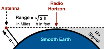
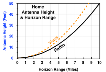
Antenna height determines the radio horizon range. The higher the antenna the greater the range. Signals can go past the Radio Horizon, but not over it. The radio horizon is greater than the visual horizon. In the atmosphere radio waves bend slightly with the earth curvature increasing the range about 15%.
The 4/3's Earth Radius model is used to estimate Radio Horizon. The model uses an earth radius that is 33% greater than actual. The radio horizon range (R) in miles is the square root of twice the antenna height (h) in feet above ground level (AGL).
| R = ( 2 h )0.5 | |
| R = | Radio Horizon Range in miles. |
| h = | Antenna Height in feet. |

| Calculate Horizon |
|---|
|
Antenna Height (h) |
|
HORIZON |
Home antennas within the tower radio horizon will usually get a signal. Antennas a few miles outside a broadcast horizon can get a signal if the home antenna is high enough and above ground clutter.

|
Calculate Range Smooth Earth |
|---|
|
Tower Antenna Height |
|
Home Antenna Height |
|
HORIZON RANGES |
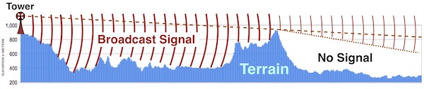
Broadcast towers are often located on the highest ground in the area, increasing horizon range. In this case the broadcast antenna height used for calculations should be the antenna height above average terrain (HAAT).

RF Ducting
A few times a year atmospheric conditions cause a ducting effect extending radio horizon. Signals are ducted along a horizontal layer in the atmosphere. The right temperature inversion, warm and cool air reversed, bend a signal toward the earth increasing range. Range can increase 10's to 100's of miles.
The condition typically last minutes to hours, and usually occurs late night to just after sunrise.
GROUND LOSS
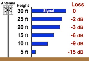
The higher the antenna is above ground level (AGL), the greater the signal density and the lower the ground loss. Antennas 30 feet or higher capture the full signal. Below 30 feet ground reflections cause multi path interference. The lower the antenna the greater the loss. Antennas in a city have more loss than in a residential area, which has more loss than a rural area. Except in rural areas, UHF signals have greater loss than VHF signals.


| Antenna Height Loss |
|---|
|
| Calculate Antenna Height Loss |
|---|
|
ANTENNA
Height: Area |
|
Height |
The L-R model (Longley-Rice propagation algorithm) is used to estimate antenna height ground loss.
| Antenna Ground Loss |
|---|
|
dB Loss = ( A/6 ) 20 Log10( h/30 )
h = Antenna Height in feet (≥ 1.5 ft). A = Area Factor |
| Area Factor ( A ) | ||
|---|---|---|
| AREA Rural Residential City |
VHF 4 5 6 |
UHF 4 6 8 |

BEAM LOSS
An antenna has maximum gain when the main beam is directly aligned (0°) to the signal direction. Gain decreases slightly from the beam center (0°) to the beam edge. At the beam edge the antenna gain is down by -3 dB. Past the beam edge (the -3 dB point) gain drops dramatically. Side and back lobes have a negative gain, from -10 dBi to -30 dBi or more.
FREQUENCY LOSS
Gain varies with frequency. The higher the frequency (higher RF channel) the greater the gain. Advertised gains are usually for the highest frequency, and the highest gain. Gain frequency variation is typically 2 to 4 dB or more.
POLARIZATION LOSS
Polarization is the broadcast antenna signal electric field orientation. Polarization loss occurs when the transmit antenna does not match the receive antenna polarization. Virtually all home antennas and many broadcast antennas are horizontally polarized. Some broadcast use circular polarization for better signal propagation in a cluttered and/or bad weather environment. When a mismatch occurs, the receive antenna loss is -3 dB.
BROADCAST PATTERN LOSS
Broadcast antenna patterns can be omni directional (broadcast equally in all directions - 360°), or directional. A home antenna that is outside a directional broadcast main beam will receive less power. The loss can be a few dB to 10's of dB's.
SUMMARY
| SOURCE | Loss |
|---|---|
| Main Beam Loss: | 0 to 3 dB |
|
Gain Variation for Frequency : |
0 to 4 dB |
| Polarization Loss: | 0 to 3 dB |
| Broadcast Pattern: | 0 to 10 dB |
Terrain Masking
TV signals require a clear line-of-sight between broadcast and receive antennas. Large obstructions and terrain features like hills and valleys can completely block a signal.
Terrain Loss
Terrain loss occurs when the ground interferes with the signal free space region. The region is shaped like an ellipsoid (a cartoon cigar shape). It's size varies with frequency and range. Near an antenna the region's radius is a couple of wavelengths, or about 4 to 30 feet. The region is largest at the midpoint. Terrain losses can vary from 1 to 12 dB or more.


Any object in the signal path can cause a signal loss. Structures and trees can measurability reduce or block signals. Tree loss can be roughly estimated. Trees without foliage (in winter) may have slightly less loss (about 1 dB) at UHF frequencies.

| Distance feet |
VHF dB |
UHF dB |
|---|---|---|
| 20' | 3 | 4 |
| 40' | 4 | 6 |
| 60' | 5 | 8 |
| 80' | 6 | 9 |
| 100' | 7 | 11 |
| 200' | 10 | 16 |
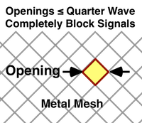
| Band | Openings less than |
|---|---|
| UHF | 5 to 6 inches |
| VHF | 1 to 4 feet |

Attic Antenna
A 3/4 inch plywood roof with roofing paper and 1 layer of 3 tab asphalt shingles will reduce a signal by about 3 dB. Slate, concrete and clay tiles have more loss. Roofs with solar panels will greatly reduce or block signals. All metal roofs block signals. Also, attic vents reduce or block signals. Metal backed insulation will block signals,
Room Antenna
Signals can not pass through metal objects. Wall air ducts and metal awnings will reduce and can block signals. Signals that pass through objects will lose some signal strength, the loss depends on the material. Glass has the least loss. Bricks, cinder blocks, and concrete have the most loss.
| Windows / Siding | Loss |
|---|---|
|
Glass 0.25 in thick Glass 0.5 in thick Glass Block |
1 dB 2 dB 6 dB |
|
Vinyl Siding Brick 3.5 in thick Brick 7 in thick Brick 10.5 in thick Metal Siding |
2 dB 3 dB 5 dB 6 dB Blocks |
| Walls etc. | Loss |
|---|---|
|
Wall Insulation Plywood Plasterboard Drywall Marble Wall Metal backed Insulation |
< 1 dB 2 dB 2 dB 3 dB 4 dB Blocks |
| Wood Door | 3 dB |
| Attic Roof | ≥ 3 dB |
| Cinder Block / Concrete | Loss |
|---|---|
|
Cinder Block 8" wide Cinder Block 16" wide Cinder Block 24" wide |
11 dB 15 dB 25 dB |
| Concrete Brick 7.5" thick | 13 dB |
|
Concrete 4" thick Concrete 8" thick Concrete 12" thick |
11 dB 21 dB 32 dB |
Loss estimates are for UHF frequencies. The VHF band is less lossy, by 1 dB or more.
SUMMARYAn antenna mounted 30 feet above the ground in a flat open field with a clear line-of-sight and aligned to the broadcast tower would get an optimum signal. Air moisture and temperature will reduce signal strength, especially in the UHF band.
| SOURCE | dB LOSS |
|---|---|
| ANTENNA | |
|
Height Ground Loss: Propagation Losses |
0 to 20 0 to 10+ |
| TERRAIN | |
|
Ground Clutter: Terrain Loss: Masking: Radio Horizon: |
0 to 15+ 0 to 12+ No Signal No Signal |
| INDOOR | |
|
Attic Antenna: Room Antenna |
3+ 1 to 11+ |
|
OTA DTv TV Signal Factors |
|
|---|